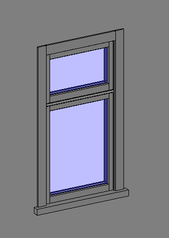
Here is an example:
I have "happened" on a set of plans which were about extending one of these, and used it to sharpen my Revit skills. Confirmation that Autocad would be a silly way of doing one of these houses would require the same house to be drawn in Autocad solids.
In the Autocad process I found it necessary to draw 14 different but similar windows to suit the various sizes needed. This seemed to take forever, even using my special lisp routine to draw wooden windows automatically. It would have taken a lot longer manually doing them from scratch.
You can catch a video of this here: https://www.youtube.com/watch?v=AMLeBgPqOqs
Of course you end up cutting and stretching similar ones, but it is still a lengthy process.
I drew the Autocad one first and then the Revit one second. Half way through the Revit one I ran out of steam, due to a diversion into the land of families. I have made several wooden window families, but do not consider myself an expert on these as yet. For instance: do you make them for one wall thickness or should they adapt to all? So only a few windows were made. Half way through this process I realised I should be using "nested families". This is where you make a sash that fits in several windows. Again, this is a lengthy process, and full of learning curves.
Here is the Autocad house:
Straight away you can see that there are no materials applied (but they could be).
Here is the same house in Revit:
Here you can see the outer cladding is showing up, as is the "tin" roof.
With the Autocad drawing the best way to approach the floor plan is to xref the model into a completely new file, and issue the SECTION command. Here are the results of doing that:
This is just a screen shot (built into Autocad but not revit-all my Revit pics here are using the Windows Snipping Tool).
The Revit one is automatic and looks like this:
This looks a bit more up market than the Autocad one- I would have had to add doors manually in the Autocad one. Score 1 here for Revit.
Now we get into the "symbolic lines" thing of Revit. As I understand it, you can draw a window family in Revit, and only bits of it will come out in a plan view. The reason for this is performance, and at a 1:50 scale is there any point in getting excited?
Here is an Autocad window section:
As you can see, all the solids are shown realistically.
This is a Revit window section, one which I did not add symbolic lines to:
I can hear someone saying, "Ah yes, but you can add these symbolic lines to the window family!"
Well, yes you can, but make sure that they are all constrained and locked, otherwise they go all over the place. I am tempted to say "Score 1" for Autocad here.
Sectional views:
Here is the Autocad one:
Not pretty, but mostly there.
The Revit one shows the doors, so maybe a score for Revit on this one:
Notice the Revit one has a generic "thick roof", with no purlins shown. They could have been. It seems an uphill mission to do a roof with rafters/purlins/tin in Revit. I am probably doing it the wrong way. The normal way is to probably draw them in using 2D lines. It is also a pain to do in Autocad, but placement is easier and more precise. The nice thing about doing them in solids is that the roof plan is ready to go.
Here is my double sash window:
I am quite pleased with this, especially the horizontal transom which misbehaved until I struck on the novel idea of locking all the lines together in the outline of the extrusion then having just one locating dimension, as shown in this side view:
This window can cope with user defined sill height, height, width and distance down to the transom from the top. Making double, treble and quadruple ones can wait until I actually get a job that needs them.
Maybe I am not looking in the right places, but I could not find a Youtube video of transoms with strange profiles, and how to do them.
Conclusions:
Autocad is a great general drafting/modelling program, of great antiquity (around 1982). That you can model a house in it speaks volumes for it's versatility. Revit on the other hand just does buildings, although it can draw things like ovens and range hoods for use as content.
The fact that I had to draw 14 different Autocad windows indicates this could be a time waster on most jobs if you used Autocad. On the plus side for Autocad is the precision and ease of placing things like rafters and so on. It has to be said though that Revit's beam system would be the equivalent of this, one which needs practice to get used to coming from an Autocad background.
I have not looked into the automation side of Revit, but no doubt something could be done to produce a roof that has rafters/purlins/tin all in one hit.
Revit has a very easy to use rendering system, and would score better in production of door and window schedules, especially as any change any where is reflected in all views. In Autocad, you would make changes to your model, then go into the sectional drawing and press the update button on the section tool.
Revit's materials seem to be built in, so concrete comes out hatched in a section as concrete. To get the same in Autocad you would have to have no hatching in the sectional view and then add concrete hatching manually.
Getting your window content directories full means trips to a site where you have to pay for such things. One in NZ is: http://www.cadcontent.co.nz/


