Sunday, July 19, 2015

Wall layers at different heights and misbehaving windows

Wall Layers

Would it not be nice if software developers put meaningful labels on their buttons?

Here is a typical example in Revit: You want to let the weatherboards hang down a little lower than the main framing.  How to do this? Well, covered very well in this blog here:

http://www.revitzone.com/3d-modelling/182-walls-extending-individual-layers

To get to the part you need, you hit a button marked "Preview".  Not intuitive.

This is the dialog box:


Then you get another dialog box with a side view on it, where you click on the layer you want to alter then you unlock it.  Then you come back out back to the Properties and you find that you can now edit the "Base Extension Distance".  Admittedly, what would you label that button?  "Hit this to stuff around with wall layers different base offsets"?  Obviously not enough room for that...Or how about:
"Wall Layer Modifications"  or "To Alter Wall Layers"? Even then, how would you know to click on the layer and unlock it?

I guess it is one of those "need to know" things that all software seems to have.

Misbehaving Windows

A friend is making  a set of wooden windows for an architecturally designed house.  I thought this would be a good opportunity to demonstrate my skills in detailing in 3D the details of the strange track system for the sliding door.  The architect did not want a guiding track to be visible as you exit the door.  The solution was to put the track under the sill.  I had not any real problems drawing up the brackets and roller for the door, as seen below:


The fun came when I chose to insert it into the project.  It would not go in.  After getting the problem solved by going to the Autodesk Revit discussion group, the sins of my family were put on display.
My sin was to have a certain thickness of wall in the family and another one in my project.  Not so bad but somehow I had managed to constrain the door part to the wall.  A constraint not needed as it happens!

In the process of detailing the rollers and so on, I have come to realise there are no fasteners in "out of the box" Revit.  Why not? I guess they are already overloaded in the download department.  Could they not make it a separate download? OOPs! Just did a google check and Autodesk Seek has them!

See http://seek.autodesk.com/category/locale/USRevitStr/05090-Metal+Fastenings


Wednesday, June 24, 2015

Revit Frustrations

You can have a bit of fun with Revit.  Designing houses.

The drudgery begins when you have to annotate stuff like a roof truss layout.

I have this crazy idea that if I prepare a full set of construction documents, I can use these to get a job. I'm almost put off by my attempts to do this, compared to using plain old Autocad.

Part of the problem is my choice of paper size.  I chose A3, thinking it would be nice and cheap to get photocopied as opposed to as A2.   My set of plans done back in 2005 used A2, consequently text sizes were able to be a lot smaller, and the plans could be at 1:50, not 1:100.

This is the difference:

This first one is the Autocad one done in 2005


This is the Revit one.  Looks very crappy!

I have ended up with the second floor structure horning in on things, because it is made out of wood framing, as is the roof framing!  To get the ground floor framing to appear nicely dotted, proved a bridge too far, as overriding the visibility graphics with a dashed line did not seem to work.

To mark the lintel positions, I resorted to a filled region rectangle. Why does Revit not have a polyline tool?

Then I got into changing the scale of the plan from 1:50 to 1:100, and found my section bubbles disappeared.  Half an hour of internet searching later, I find there is a little button on the view properties called the View Scale, and you have to change this.

Then I see that my Level that I labelled Ground Level Lower decided 1 line was not enough and put it on 2 lines.  Fine, except that the word Ground ended up on top of the number and with seemingly no way of moving any of the items or specifiying only one line, I gave up in disgust.

I can only imagine the frustration levels of some Revit beginners, under pressure to get some plans out the door, and they come across this sort of stuff.  

I thought it might be instructional to download a set of Revit plans for a plain old New Zealand house. You would think there would be hundreds available for download.  Nope. Zip. NADA!

Maybe I am looking in the wrong places?


Tuesday, June 16, 2015

Just a post on Posts

Well, here I am 6 months later and still not a Revit Guru.  Admittedly, I did have to shift house in there somewhere.  I downloaded the building suite stuff and had fun with Showcase- see my Youtube video here: https://www.youtube.com/watch?v=y58uSkHQvgk

I am at the quite nice position now where I can watch a Revit video and say things like: "He should have done that in 3D", and "Does he not know to extend a fascia by the grip on the end?"
Then I look at some of the sites talked about below and realise, I am still around 40%.  It would be better to be around 80%.

I have dropped my resume at about 3 architectural practices here in my small town near Auckland.
No luck so far.  I cannot really blame them really, as they want people with about 1 -2 years experience.  With my yearly subscription rolling up in about 6 weeks, I may have to take the hard decision of pulling the plug on software upgrades.  I have the building suite - ie Autocad, Revit etc.

There seems to be quite a demand for such people at the moment, but the situation in NZ is by no means sure as we are not getting enough for our dairy produce to give a lively economy.

I find I am getting stuck on alleyways in Revit and going around in circles, because I do not understand the basic principles of modelling in Revit.

All the bits below came about because I wanted to draw a simple day light angle- the sort that goes up by 2m then back in at and angle of 45 degrees to give an allowable building envelope.

This led me to fences and topos :  all I want is to put a fence on a topo surface.  After much research, I found two different, but related techniques:

1. Use Dynamo to essentially draw a line in plan view on your topo and a fence magically appears.
You can check out this at http://plevit1.blogspot.kr/2015/04/railing-on-topography.html
This is a program by HyunWoo Kim, a Korean who seems to be immensely intelligent and a very clever user of Revit.  You do have to download the Dynamo file and the family it uses, and install Dynamo on your Revit as an add-in.

2. Draw mass on  top of your topo, then draw a reference curve on the edge where it intersects.  Then you Divide this curve into a series of points, in this case 2000mm.
You can check out this method at: https://www.youtube.com/watch?v=oZ3KIgOyzkE
Again, you need to either download a family, or make your own.  This guy does a very good job of explaining himself as he goes along, producing a tube style handrail that does the job nicely.  At the end he shows the same method , but for a standard wooden fence this time.  Unfortunately there is no explanation of how the family was constructed, leaving me to struggle for 3 days on my own.

Time for a pic of one of the blind alleys:

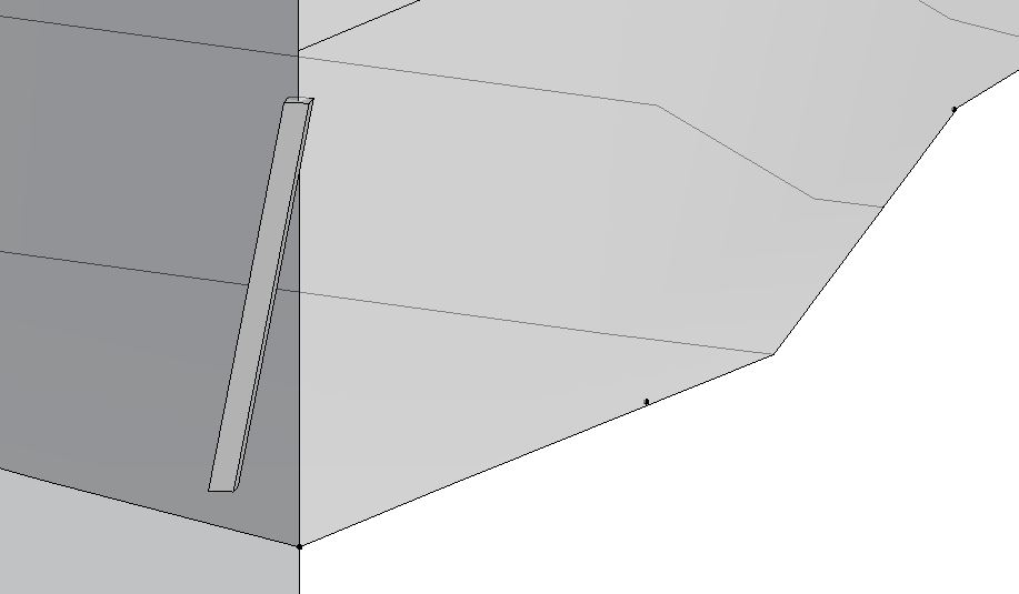
As you can see the post ended up a bit tilted.  This could be useful one day?

Success came with much effort later:
Fence posts....Hooray!
After even more effort came:
Which is where I am going to declare a minor victory, though the picky might grumble that there are no planks or stringers shown.

All this is enabled through the creation of an adaptive family, which is used in  both of the methods mentioned above.

Easy enough to make after the explanation given in the Youtube videos, except for the panel bit.

In the end, I just banged in 4 reference points, then drew a model line using those points, and made a shape out of them , setting the extrusion value to 20mm.


In the end, I could not get the Dyanmo one to work on my topo, which I suspect is because my topo is 85m up off the ground level.  

The Dynamo one is definitely the quicker of the two, and I predict this is where Revit is heading to.
Have a look at HynWoo Kim's spanish tile roof demo - mind blowing!


Tuesday, February 24, 2015

Using Autocad solids versus Revit for a residential house

In New Zealand we have these styles of houses called "California Bungalows".  They were fashionable around 1920 or so.  Their characteristics are: Wooden framing, wooden weatherboards, wooden windows and a corrugated iron roof.  They usually had a bow window.

Here is an example:


I have "happened" on a set of plans which were about extending one of these, and used it to sharpen my Revit skills. Confirmation that Autocad would be a silly way of doing one of these houses would require the same house to be drawn in Autocad solids.

In the Autocad process I found it necessary to draw 14 different but similar windows to suit the various sizes needed.  This seemed to take forever, even using my special lisp routine to draw wooden windows automatically.  It would have taken a lot longer manually doing them from scratch.

You can catch a video of this here: https://www.youtube.com/watch?v=AMLeBgPqOqs

Of course you end up cutting and stretching similar ones, but it is still a lengthy process.

I drew the Autocad one first and then the Revit one second.  Half way through the Revit one I ran out of steam, due to a diversion into the land of families.  I have made several wooden window families, but do not consider myself an expert on these as yet.  For instance: do you make them for one wall thickness or should they adapt to all?  So only a few windows were made.  Half way through this process I realised I should be using "nested families".  This is where you make a sash that fits in several windows.  Again, this is a lengthy process, and full of learning curves.

Here is the Autocad house:


Straight away you can see that there are no materials applied (but they could be).

Here is the same house in Revit:

Here you can see the outer cladding is showing up, as is the "tin" roof. 

With the Autocad drawing the best way to approach the floor plan is to xref the model into a completely new file, and issue the SECTION  command. Here are the results of doing that:


This is just a screen shot (built into Autocad but not revit-all my Revit pics here are using the Windows Snipping Tool).

The Revit one is automatic and looks like this:
This looks a bit more up market than the Autocad one- I would have had to  add doors manually in the Autocad one. Score 1 here for Revit.

Now we get into the "symbolic lines" thing of Revit.  As I understand it, you can draw a window family in Revit, and only bits of it will come out in a plan view.  The reason for this is performance, and at a 1:50 scale is there any point in getting excited?

Here is an Autocad window section:


As you can see, all the solids are shown realistically.

This is a Revit window section, one which I did not add symbolic lines to:


I can hear someone saying, "Ah yes, but you can add these symbolic lines to the window family!"
Well, yes you can, but make sure that they are all constrained and locked, otherwise they go all over the place.  I am tempted to say "Score 1" for Autocad here.

Sectional views:

Here is the Autocad one:


Not pretty, but mostly there.

The Revit one shows the doors, so maybe a score for Revit on this one:

Notice the Revit one has a generic "thick roof", with no purlins shown.  They could have been.  It seems an uphill mission to do a roof with rafters/purlins/tin in Revit.  I am probably doing it the wrong way. The normal way is to probably draw them in using 2D lines.  It is also a pain to do in Autocad, but placement is easier and more precise. The nice thing about doing them in solids is that the roof plan is ready to go.

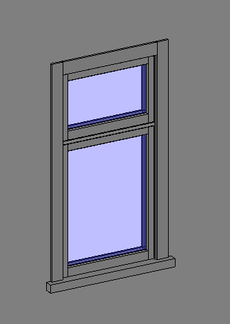
Here is my double sash window: 


I am quite pleased with this, especially the horizontal transom which misbehaved until I struck on the novel idea of locking all the lines together in the outline of the extrusion then having just one locating dimension, as shown in this side view:

This window can cope with user defined sill height, height, width and distance down to the transom from the top.  Making double, treble and quadruple ones can wait until I actually get a job that needs them.

Maybe I am not looking in the right places, but I could not find a Youtube video of transoms with strange profiles, and how to do them. 

Conclusions:

Autocad is a great general drafting/modelling program, of great antiquity (around 1982).  That you can model a house in it speaks volumes for it's versatility.  Revit on the other hand just does buildings, although it can draw things like ovens and range hoods for use as content.

The fact that I had to draw 14 different Autocad windows indicates this could be a time waster on most jobs if you used Autocad.  On the plus side for Autocad is the precision and ease of placing things like rafters and so on.  It has to be said though that Revit's beam system would be the equivalent of this, one which needs practice to get used to coming from an Autocad background.

I have not looked into the automation side of Revit, but no doubt something could be done to produce  a roof that has rafters/purlins/tin all in one hit.

Revit has a very easy to use rendering system, and would score better in production of door and window schedules, especially as any change any where is reflected in all views. In Autocad, you would make changes to your model, then go into the sectional drawing and press the update button on the section tool.

Revit's materials seem to be built in, so concrete comes out hatched in a section as concrete.  To get the same in Autocad you would have to have no hatching in the sectional view and then add concrete hatching manually.

Getting your window content directories full means trips to a site where you have to pay for such things.  One in NZ is: http://www.cadcontent.co.nz/

To sum up then: Revit is a winner over Autocad if you are drawing houses. 


Friday, February 20, 2015

More on Revit Massing

My last post was a bit cryptic, so here is a slightly more verbose version:

You create a Mass family file.  In the creation of the file you have good control over the solids you are drawing and the file I drew ended up looking like this:


A bit grey and bland.  

Then you open a new project and bring in this family.  Then it is just a matter of choosing the Massing & Site tab and picking on say Roof and picking what you want to be a roof etc.

Then it ends up looking like this:


Of course at some stage in a perspective view like this you have to hide in the view the mass, otherwise it shows through as a grey shape under everything. This building shown has been moved on from this stage - it seems architecture might be an iterative process after all?


Monday, February 16, 2015

Revit Massing: It's a wonderful thing

So excited that I actually got something done!

Looking at this series of 3 videos certainly helped.  The only drawback is the audio quality, but the series is easy to understand and copy.

https://www.youtube.com/watch?v=00Uo8gIc1YU

I can imagine the average architect would be impressed by the ease of use of massing.


This all took about 1/2 hour to do.

Time to stop mucking around?

My Revit journey is inching towards something or other.  Namely, a certain level of competence in the use of Revit.

To this end, Robin has kindly lent a book, "Mastering Autodesk Revit Architecture 2011" by Eddy Krygiel, Phil Read and James Vandezande.  A total of 1122 page, and weighs in around 2.3 kg.  Not a complete beginners book it goes into such areas as Film and Stage and Revit in the Cloud , which I am not going study.

Up until now, I have just picked up a project done previously in Autocad and redrawn it in Revit.
While useful, it seems a bit of a disorganised approach.  So I have taken stock of what I do know, and used the headings in the book as a guide for a sequence of study to be undertaken.

This is my list:

1. Advanced modelling and Massing
2. Walls and Curtain Walls
3. Floors, Ceilings and Roofs
4. Family Editor
5. Stairs and Railings
6. Detailing
7. Documentation
8. Annotating
9. Presentation

My present situation is that I threw in my mechanical drafting job on the 19th January 2015, hoping to get a change of scene by drafting houses instead.  This ties in with a desire to work at home, seeing as I have Revit 2015, along with Autocad etc.  I have approached about 8 local architects with an offer of a fixed price per square metre for residential house drafting, but no takers as yet.

Just trolling through other Reviteer's blogs is a depressing journey: I realise how little I know.

Some blogs stand out, this one I like and will be going back to: http://revitrants.blogspot.co.nz/

Just because drawing a wall and inserting a wall is very easy in Revit can lead you into the false idea that this is an easy program to master.