Sunday, February 21, 2021

Site Measures ,Presentation of Elevations and Snaps

Site Measures

After much pain, I have come to the following conclusions:

1. If there are site dimensions to be measured, get the guy who is going to be drafting to do the site measures.

2. If he thinks 2 hours might do, multiply this time by 3 and tell him you are fine with however it might take.  Never skimp on time for site measures.

3. Do NOT TRY TO FIT A WHOLE HOUSE ON ONE A4 SHEET!  Apologies for the caps, but this cannot be stressed enough.  Make it one room per A4 sheet.(Letter in USA).  The number of times I have been handed illegible microscopic scribbles......&****@@@!

4. Take photos. Lots of them, from as many different angles as you can. In my experience, there is always about 5 views I wish they had taken.

5. If you are doing a string of dimensions, do an overall one to check that they add up to the overall, which means taking a calculator to site. 


Presentation of Elevations

On a recent job, I thought, yippee, let's push the boat out and have shadows on and ambient shading and turn on realistic.  Fine if you have a colour printer, but not if they are printed out, as they come out quite dreary and dark looking.

A better alternative is to leave shadows off and just have ambient shadows.


As the building had board and batten cladding it seemed originally a good idea to have the rendered appearance to show the board and batten.  Turns out a much sharper result is obtained by using surface hatching.  Revit does not have a board and batten hatching, but you can download one of these patterns.

I found one, and a shout out here to Robert Cloward, who posts these for free. Thanks Robert.

Here is the contents of one, to view, just change the file extension to .txt and use the text editor to look at it and maybe vary it's contents: 

;%VERSION=3.0

;%UNITS=INCH

;;

;;

;;     Custom hatch pattern by Robert Cloward

;; December 2007

;;

;;

*B&B-12x1, Batt & Board 12 in board 1 in spaces

;%TYPE=MODEL

90, 0,0, 0,12

90, 1,0, 0,12

This turned out to have 1" wide boards about 12" apart.  Not what I wanted, so I turned the 1 to a 2 and the 12 to an 8.  Then resave the file as a .pat file.

Snaps

I have never taken much notice of these, consequently a lot of my drawings are not terribly accurate. In a bout of Revit frustration I opened up the snap dialog and the source of all my wrong doing became apparent.....ALL SNAPS ARE ON!  In an Autocad world many years ago, I had a routine that turned on a few snaps on and all was reasonably accurately done.  Then I worked at a place where a man had every snap turned on.  Yup, he was a lot faster, but not very accurate.

I see from the dialog box you can turn on a particular snap, say midpoint by typing SM in the middle of the command, so I am going to try setting mine to just endpoints and midpoints and dialling up any others as I go for a while.


Sunday, January 17, 2021

Custom Elevation Markers and Large Site Drawings

Well, here we are in 2021 and I am still finding some work, albeit a bit spotty,  hence I have the day off today.  As well as the last 5 days.

Elevation Markers

On one of my jobs, the Licensed Building Professional who gets to sign off my work (I live in New Zealand and you cannot submit work unless you are a Licensed Building Professional) wanted me to change my elevation marker from the Revit out of the box one, namely:


Because I felt under pressure to get stuff out, I fired back a message saying it could possibly be changed, but I would take and hour just to figure out how to change it, and could we please leave it as it is?

His reply:

I've noticed similar limitations with ArchiCad and other programs used in my old office - that one is limited in terms of notes, detail tags etc & drawing presentation is dictated by the program itself which is why prefer to stick to Autocad for drafting - if i can't get my plans to look the way i want them then who controls who - a program controls me or I control the program?


You can see my point?
These flash programs are def good for 3Ds and animation but i'm still not convinced when it comes to consent plans & working drawings which is why I stubbornly stick to good old Autocad"

So with some spare time, I tried to modify an apparently simple little item.

After some nasty warning dialog boxes as I moved down a track that Revit obviously disapproved of, I saved the drawing under a new name that had "test" in it!

It turns out that the marker is composed of two pieces:

1. The body, ie the circle
2. The pointer, which is a separate file.

You can modify both, just save them under new names.

My mistake was to try and rearrange the item number in the arrow family so it might turn up in the right place.  Wrong!  The correct plan is to delete the number off the arrow completely.
Then in the body, add this as a label so it displays above the sheet number, which you move down and put in a line to separate the two.

As in the following:


Which is great, except that now for some reason the arrow is not filled.  After much puzzlement and looking, the solution to that was to go into the family, and delete the existing filled region, and draw in a new one.  Go figure!

Here we are, success at last:


Large Site Drawings

On another job, another different architect had already drawn his development of 14 homes on one property.  This was split into two buildings, one of 4 apartments and the other of 10.
The 10 unit block was on 3 different levels and the 4 apartments on yet another set of levels.

All I had to do was a few sections and a few details so he will be able put it in to Council for Building Consent.  A typical Bill estimate would have been 40 hours. 

Ever heard of the Bill factor? If Bill says it will take 4 hours, to get the actual time taken, multiply this by the Bill factor, usually 5, so in this example, it would be 4x5=20 hours.

He wisely never asked me how long I might take!.  Well, 2/3 done at the moment, and nearly 100 hours have gone by.  Part of this is my fault: I have modeled every stick of wood in the roof of the 4 unit block. A mistake I will not make for the larger block.

I found much of my time wasted tripping over the levels of the other block.  This is a bit of a dilemma: do you split such a development into two separate projects, making mixing of levels not an issue?  Then how to join them up together again, with details etc being common across the two projects? Then printing out two separate files and joining the pdfs together?

Another hassle was Key Notes.  I had not used these before, but I can see they are definitely a wonderful thing.  The idea is you have a text file, kept separate but in the same directory as the drawing  This is a tab delimited file containing all your Key Notes.  Great idea, just not that much fun formatting the bits as they arrive in your sheet.  Yes, you can split them so they can be spread across your page, but the final format looks a bit clunky. 

The architect has seen them and is not accepting of their formatting.  They will have to be redone as pieces of text. 

Not only that, but it seems you cannot (at least as far as I can find) use these in conjunction with detail views. No doubt on the Revit Kid's wish list?

Another fun, time consuming rabbit hole was trying to do the sanitary piping, which required the old dog to learn the new trick of Revit piping.  A quite impressive part of Revit, it just needs a lot of fiddling around loading plumbing fittings.

Yet another mad item was bracing grid lines. I thought, why don't I use the grid item to do
these? WRONG!  Every plan view I had (and there were lots) , sprouted these durn grid lines.
The only way out was to hide items in the views.  Hours later....


Saturday, July 20, 2019

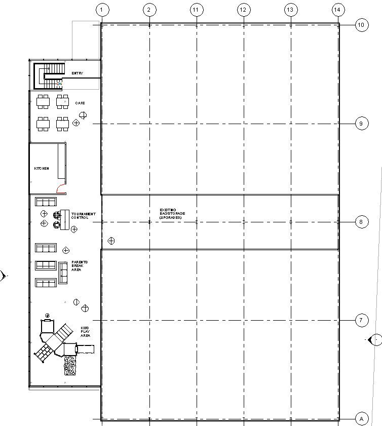
Ray Phillips Hall, at 41 Elliot Street, Papakura, Auckland, New Zealand, Addition

 Ray Phillips Hall, at 41 Elliot Street, Papakura, Auckland, New Zealand.

Just a bit of background: This hall has 6 courts.  At one stage some enthusiasm was mustered towards the building of another 5 courts. 

Unfortunately, funding did not quite meet the expected cost, so the idea was shelved, and the funds raised were put in an account, not to be touched, to await the day when it may be possible to raise enough capital to make it happen.

As a player at the hall (The Papakura Ladies Day Badminton Club, yes, I know but they allow men to play!), I was talking to someone and somehow this idea came up: Why not use the money to have a partial add-on?

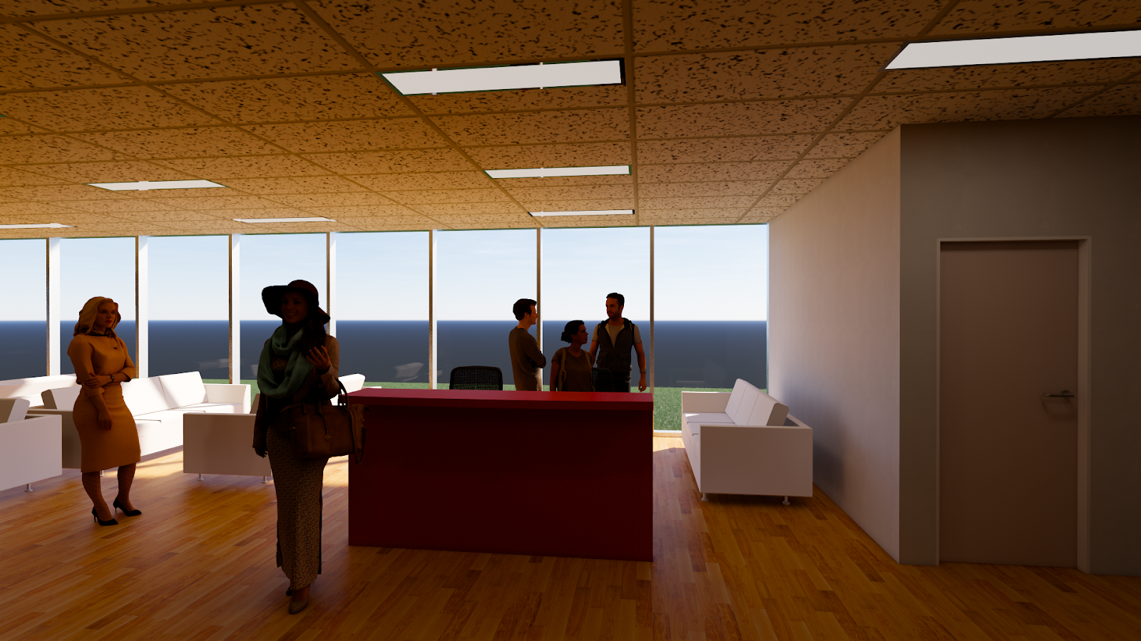
The ideas mentioned were a kids area, a proper commercial kitchen, a seating area and the ability to watch games from a different angle.

The whole idea of these plans is as a starting point. 


Friday, July 12, 2019

Hedges and True North

I have posted a video on Youtube on these, found at:

https://www.youtube.com/watch?v=JzmjvXZWtnA


True North:

There will be some who say: "Just so bleedin' obvious, why post about this?"

But there will be some who say that they have tried to mess with the True North business,  but were put off by the usual unusual way of Revit!

I was one of these, but now I realize my fears on this were unfounded.

On trying it out for the first time, my impression was that all my drawing from then on would be on a slant.  Which would be true, if you did not change the view properties back to Project North.

In hindsight, it is a nicely arranged system.  You have two options for a View Orientation, True North and Project North.

As you start a project, both Norths are set pointing up the page.

For ordinary drawing you can leave them like that, no problems.

The fun only begins when  you wish to use say Enscape to do a rendering.  Enscape checks out where your North is, and positions it's sun accordingly.

By the way if you have not tried out Enscape yet, give it a try, an amazing piece of software.  Just make sure you have an Nvidia P2000 to make it run though (cost NZ$800 or so)

To alter your project north just click on Manage and find the button to adjust True North.  A bit of strangeness here: you have to pick where the north is first and then turn the pointer to where it will be. Feels unintuitive, but that is probably just me!

To go back to normal viewing of your plan view, just set your Orientation back to Project North.

Hedging: 

I had a job recently where the client wanted some hedging out front, so I was able to make a fairly rough effort by using a wall and making it's material a piece of seamless hedge image, which I found really quickly on the internet.  It might have been even nicer if a finer image had been chosen, this one is 215x215.

Here it is:

Another better approach might have been to us a mass, and round  its edges slightly.  By this time I was in "I am over this stuff", attitude, never good, because it is always the tiny little bit of extra entourage or effort that result in a better job.

This is how the job ended up, a quadriplex, trying to get it approved by town planners:
(Notice the hedge at the front)


Wednesday, May 15, 2019

Massing, and getting two beam systems to live nicely together

Mass Objects

Recently, in fact the house that featured in the last post, I needed to put a picture frame around two windows.


Easy, you say, just draw a mass object and job done.  Well maybe not for me!  I think I may have had 3D snapping on, and this caused a lot of pain and woe.

It seems Autocad is a shovel. You can see it, you know what it does, and it is straightforward.
Revit on the other hand is like a magic black box.  You poke it and hope something comes out.

You just have to know it's little ways, which in my case is taking years to find out.

Mind you it could be me. I spent years learning Autocad.  Then at work a person who had never used Autocad got a job in our office. She knew Archicad, and maybe had a quick lesson or two on Autocad at Drafting School, but just came in, sat down and away she went. No questions, just hit the ground running.

I was amazed, this should never happen!

Anyway, with the mass thing I eventually cracked it and put a youtube video up which describes my way of doing it.

I have since found that you can use "generic models" for this sort of thing, and they might be a bit more versatile.

Here is the link: https://www.youtube.com/watch?v=le60u8EUx1M

Two Beam Systems Together

In this case I was having the decking, made out of a beam system, to sit on top of a set of joists, also a beam system.


Silly me. I found that the minute you put them together, bad things happen!

After much puzzlement, wailing and gnashing of teeth, I found a work around:

Put one beam system on one level and the other on another level, then offset the top one down so it seems to sit on the lower one.

I did make an error in the video, not a big one, but with the 92mm plank I tried to align it with the deck edge, but my first pick should have been the deck edge. Maybe this is just me, but I find this sequence even now, unintuitive.


My Youtube video showing this is at: https://www.youtube.com/watch?v=ZctXYJsyCH4

Friday, April 5, 2019

Yet More Enscape

Recently I had a request from a friend to do a house render.  Unfortunately this one was a "free" job.
As usual, it was like dragging a cat backwards through a gorse bush.  New Revit learning stuff had to go on, mostly in the area of screens, where I found out the best way was to use a curtain wall as the best way to create these.

Another pain in the butt was the fascias, which had to be shiplap.  If they were to be horizontal, then no worries, just make a wall.  But this roof is at 3 degrees, so what to do?

Several brain overloads later, I realised you could use the fascia tool to achieve this.  Just a small matter of organising a profile, and having a fascia that used that profile.  Looks vaguely related to the wall cladding, which is the same stuff.

First is my try with 3DSMax


This one was done using Enscape

Saturday, April 28, 2018

Architectural Competitions and Enscaping

Just coming up for air here, after frantically entering into lots of competitions on Freelancer.

Not a lot of luck as yet, as it seems more talented persons enter into these

I am hoping that some of them might get too busy to enter or they will judge that the amount of effort is not worth it.  This seems to be the case for a currently offered mall design. There were several calls to the contest holder to increase the prize, as he wanted multiple rendered views, along with about 20 shops that were supposed to be stocked with goods.

Well, good luck trying to stock 20 shops. Obvious work-arounds were to get pics of shop walls and use them as materials on the walls, which is what I did.  I just ran out of pics to use (most pics of merchandising are never straight on, always perspective). Not to mention patience.

I did a check render using Revit and 3dsMax on really low settings and watched the result dribble onto the screen. While the lighting came out not too bad, the amount of time to get a good looking render, probably in the region of 2 hours minimum,  which was just not competitive with Enscape, where I found that if you set capture output to 4K, you get a very sharp image in around 1 minute per shot. Then there is the ease of navigating to your next shot.  Magical.

Finding the right materials is always a trick, I downloaded a pic of the Texas flag and used it on the columns, maybe a bit garish. The floor was a download as well.

Here is the front of the mall, this shot shrunk down from 11.5Mb to 89kb:


 This competition is still running, and sealed.  I guess sealed is so people do not copy each other.
Speaking of which, it appears this site gets around 50 page views per month. What is deceptive about this figure is that it covers all the posts, and does not say if they read it or not.  So to the two persons reading this, "Hello!"

The next one entered was a pair of townhouses in Australia.  Given the brief, I found it almost uncanny how the creation of the floor plan generated on it's own the "architecture".  Which is to say that very little "architectural" design was involved.  Maybe that is why it did not win.

Here it is, all 3 stories: